Principles of Digital FAbrication
Test circuit board 28.03.2018
Heading 1
This is a simple circuit design with Eagle (CAD) and made with the milling machine Roland SRM-20.
Firstly, Eagle was used for the circuit design and after it was exported in the form of a PNG image. The image 1 shows the paths of the circuit. Image 2 includes the borders to be milled out and the image 3 displays the holes used for the pins.
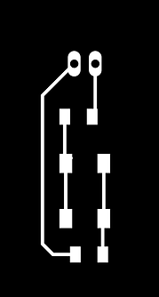
(Image 1)

(Image 2)

(Image 3)
Once exported to PNG these three images were sent to fablabmodules.org and converted there into .rml files for the milling. Once the files were ready it was time to set up the machine and mill the board.


Changing the bits for milling and exporting PNG images to .rml
After being cut out the circuit board has to be scrubbed to remove the extra coating.

With coating


Without coating
Finally, the components are soldered to the circuit. For this board I have used a resistor, a push button and a Led.

Push button
LED
Resistor


Step 1
Soldering the LED

Step 2
Soldering the resistor

Step 3
Soldering the push button
At the end, the board is connected to a power supply and the connections are checked. It works!

PRoject: bluetooth device to send lists to a smaprtphone
Concept 11.04.18
The concept of this gadget is based on the need of saving paper and in monitoring the food available at home. For this reason the gadget will allow the user to create a shopping list, previously defined by the user and send it in a text form to his/her phone.
The reason why I have come up to this gadget is because of the amount of paper used in previous purchases and for automatically record in an intelligent device the products to buy in the next shopping.
For this particular project the main materials required are:
Arduino Uno
LCD 2x16
Bluetooth component
Rotary encoder
Jumper wires
Plywood
Skecth
First draft
Final draft

The first idea was to use push buttons to select the different choices. However this idea was quickly changed.

The final idea is to use a rotatory encoder and to code a menu with different options.
Second week 17.04.18
This week the main improvements have been to get a LCD display 2x16 and to watch tutorials of how to code a menu and display it.
Also I have tried with the help of the Fablab's staff to try the LCD with a simple message like "Hello World" but with no success. As part of the problem we thought that the pads from the LCD were not making sufficient contact with the pins, thus I decided to solder it to pin legs.
This week I have learnt to wire up the LCD and the staff from FabLab taught me how to solder and use the workingstation.
Moreover, at this point of the process, I may consider the use of Arduino Mega due to the use of pins. The bluetooth module will use 2 pins, the LCD 6 pins (4-bits) and the encoder another one. Once all the components are checked individually, the decision will be made.

Future improvements for next week are:
Display a message on the LCD.
Start categorizing the options of the menu.
Design the box for the arduino.
Third week 23.04.18
Trouble shooting of the problems from week two. A potentiometer has been included in the circuit as in the original example. The new categorization of the menu is still under development. Challenges at this point of the work start to appear in varied forms. Firstly, the main concern is if the arduino will have enough pins for holding the bluetooth and rotary encoder.
This week I have learnt to read schematics of circuits and to wire up the required components to make the LCD work. Also I have been doing some research for writing up the menu. I believe that menus require "cases" to which some conditions apply.
Further development is coming, specially regarding the menu, however the main panel would look like this:
- My list: Items
Edit
Back
- Add + : Items > Subitem
Subitem
Items
Items > Subitem
Subitem
Items
Items
Back
- Send


gap (4th week until 07.06 due to work overload)
fourth week 07.06.18
This gap in the work has supposed a serious changes in plans. During this time I have had the chance to rethink my plan and objectives. At this point, due to my current knowledge of coding, the bluetooth component is dismissed from the original plan.
Having said that, during this week I have been in Fablab and got support from one of the course managers. He has helped me throughout the process but especially at this moment. I did research and got some examples of codes, but I was not able to adapt them to my needs. However, with Iván's help we were able wrote the basic functions of the code.
This week I have learnt that for the code it is better to have two menus and only one of those will be dynamic. For the items to change the status I will use a integer number, 0 and 1. the 0 mean that the item is not selected and 1 that the item is selected. Just as the binary language from computing.
The essential part of the code is composed by:
String MenuItems[size] =
This string encomprises all the items from the menu. There are eleven in total.
int State_MenuItems[size] = {1, 0, 0, 0, 0, 0, 0, 0, 0, 0, 0};
This integer depicts the state of an item. (1) means an item has been selected and (0) means not. This int varies accordingly to the main function (checkbutton) in the void loop.
bootlean checkbutton is the function that reads which of the three pushbuttons has been pressed (Add, Back and Delete). To do that, this function shows a true / false response to the action of pressing a button.
Digitalread reads the values of the rotary encoder, to determine whether it is rotated to the right or to the left. Also, the int Knobposition is used to determine which is the item where the cursor is set. The value of the knobposition changes accordingly to the changes in the rotary encoder.
Finally, the most important function of the code is the void showcurrentlistelement().
This function works on the two menus of the code. The menu 1 includes the items selected, while the menu 2 shows all the items available. This week I feel I have learnt a lot in terms of arduino´s language. I feel more confident when thinking about logic and fixing future parts of the code.
This code compiles well, but it has not been tried yet with the setup.
fifth week 15.06.18
The code from the previous week compiles perfectly but there is a problem with the function lcd.print (MenuItems[Knobposition]).
It seems that the function does not recognize the different items of the string and thus they are not printed in the lcd. I have tried as well with the serial.print and still not working.

I feel I am stuck again with the function showcurrentlistelement(). It is well coded, but there must be a problem with the logic that does not print the items in the lcd.
I have been reading in arduino´s website the descriptions of the functions write and print. According to this, the function print should display the arrays with no problem, but apparently the logic is not correct. I have been tinkering with the code and learnt that I have to use the function lcd.clear when I want to print something different from the original message. Otherwise the arduino will not print it.
To debug some other problems, I will try the components separately to check if they have any hardware damage. Also I will continue checking for a solution to the printing of the items.
sixth- seventh week 27.06.18
The components have no damage and their work perfectly with other codes. However some noise has been found in the rotary encoder and the push buttons. They send wrong signals when pressed or rotated.
In order to avoid this noise, especially with the push buttons, it was included in the code the INPUT_PULLUP built in arduino´s library. To do so the push buttons were connected to GND and signal, and the code was written in the following way:
pinMode (Pinadd, INPUT_PULLUP);
pinMode (Pindelete, INPUT_PULLUP);
pinMode (Pinback, INPUT_PULLUP);
pinMode (PinRotaryA, INPUT_PULLUP);
pinMode (PinRotaryB, INPUT_PULLUP);
I would highlight the function INPUT_
PULLUP as the main learning from this
week. I understood that there are not
absolute ceros with the INPUT as such,
and thus the signal can fluctuate. For
that reason the INPUT_PULLUP fixes this
problem.
Continuing with the past week, the same
problems have persisted. The lcd does not print the array of elements. It can be an error in the logic of the void showcurrentlistelements or that the function lcd.print does not print the elements accordingly.
At this point, I have decided to do some investigation individually and focus on solving this problem when I am back at the university. Notwithstanding, I have to publicly express my gratitude to the staff from FabLab that has been helping me telematically with the coding task. However, I am afraid that my knowledge about coding is limited, and without their help I will not be capable of advancing much in the current situation. Nevertheless, in August I will be back to Oulu and this problem will be solved.
Next entry will be in the first week of August.
LINK TO THE CODE:
https://drive.google.com/open?id=1N_oVIWIc4ueXjHDilxImlHEjnl6w6CBY

Eight week 07.08.18
The problem with the code has been finally found. There was one part of the logic missing. Neither the cursor was set, thus the function lcd.print did not have a coordinate to display the text.
In addition, we solved the problem with the logic of the showcurrentlistelement. To allow the text to be displayed in the lcd we wrote a function (void ourprint) that will be included after showcurrentlistelements and will set the cursor and clear the lcd each time there is a change in the knobposition or pushbutton.
void ourprint(String text){
lcd.clear();
lcd.setCursor(0,0);
lcd.print(text);
However, there was an issue I found in the logic of the back push button. When pressed once it was changing to menu 2 but from there it did not change to menu 1. The original code was the left one and the right one the adapted. The arrows show the problems and changes.
The way to debug and find this problem was using the serial print to check when and which button has been pressed.
LINK TO THE CODE:
https://drive.google.com/open?id=18rwCK9xPBA_gJPunXKEYf9XPDs2xLDTz
The next steps to take are the design of the circuit board, the soldering of components and the creation of the box to fit the arduino.
else if (checkbutton (Pinback)) {
if (currentmenu == 1) {
currentmenu == 2;
Knobposition = 0;
showcurrentlistelement();
;
;
}
else if (currentmenu == 2) {
Knobposition = 0;
showcurrentlistelement();
}
else if (checkbutton (Pinback)) {
if (currentmenu == 1) {
currentmenu = 2;
Knobposition = 0;
showcurrentlistelement();
;
;
}
else if (currentmenu == 2) {
currentmenu = 1;
Knobposition = 0;
showcurrentlistelement();
}

nineth week 17.08.18
For the creation of the PCB I have listed the components needed:
LCD display x1
Pushbuttons x3
Rotary encoder x1
Potentiometer x1
200Kohm resistor x1
The design has been made with the software Eagle, following the same steps as for the tryout PCB explained above. I am using an arduino shield from Eagle´s library.
During the design process I faced two main problems. Firstly, the CAD files of the rotary encoder and the potentiometer were not included in the Fab libraries neither in the manufacturer's website. Thus, at this point I decided to use three pin holes for the rotary encoder and a default potentiometer component. Secondly, there were several vias and airlines, so I had to use jumping wires to prevent routes to cross.
The designs are the following.

Inverted image of pin holes

Top layer and pads

Outline

PCB
The components are soldered to the PCB using a weller in FabLab. To make sure there are no shortcuts when soldering I made use of a magnifier lens and pliers to hold the components. The LCD is not soldered to the PCB in order to make it reusable for other projects. For doing that, pin heads were needed.


As mentioned before, I had to make use of jumping wires to avoid overlapping of routes.
Another of the problems faced once I had soldered the pins was that the pins of the LCD were reversed, thus it does not follow the original plan but still works. The PCB was working and I did not want to throw it to the trash for a small mistake.
Finally, I designed a box to protect the arduino and the shield. To do that I made use of the software InkScape and I cut the piece of MDF 3mm in the FabLab's laser cutter.


FINAL CODE:
https://drive.google.com/open?id=1MA3LPqHvkdOk3LdiF_yMKWzmsQr5GihI
PCB DESIGN:
https://drive.google.com/open?id=1DBL646g8S8WXCYxTgZpzWdN0fBwrbwjp
BOX DESIGN:
https://drive.google.com/drive/folders/1CPN1FtD0F4gB-ZCuMHeWJ2u5BWUtwWF8?usp=sharing
Final report
The aim of this project was to design and create a gadget that operates with arduino for displaying a menu in a LCD display. I came up with the idea of a "shopping list" for learning how to select, add and delete elements in a dynamic menu. I had to remove the bluetooth component because of the complexity of the project. However I retain the main aspects of the initial draft.
I had decided from the beginning that the PCB will be a shield for the arduino and that the LCD has to be removable for keeping its usability for other projects. In that fashion, I decided to add pin heads to the PCB to be able to both, plug it in and unplug it. I had used Eagle to make the PCB and Inkscape for producing the box. I thought of using the 3D printer, but I thought that the amount of material required for this dimensions was very high. For that reason I made use of scratch pieces of MDF 3mm from the Fablab. Had I had more time, I would have implemented a box with acrylic sides and plywood at the top, putting the LCD display, the push buttons and the rotary encoder outside the box.
FINAL VERSION
The artifact is composed of an arduino, a PCB with soldered components and a box. There is a LCD that displays the menus. When plugged, there is a message "Shopping list empty" and then it says "Press any button to add items". When any of the buttons is pressed, the main menu appears. This menu contains all the items available. To see them the user has to scroll down or up with the help of the rotary encoder.
The buttons have the functions to add, to delete and to go back. If the user is in the menu 1 and presses any item with the button "add", that item is stored in menu 2. Every item has at the beginning a status of 0, when pressed the button "add" that status changes to 1, and that is how the arduino understands that the item is going to menu 2. If the user presses the button "back" when being in menu 1, it will change to menu 2 even if that is empty. However, if the user presses "delete" when being in menu 1, nothing will happen.
In menu 2 the items are stored with a value of 1. If the user presses back in menu 2 it changes to menu 1. If the user presses "delete" over an item, the item's status changes to 0 and thus is removed from the menu.
Here you can see a video of the gadget in use.
NOTE: I had to wire the LCD to the PCB because as mentioned before the pins are reversed, and it is hard to film the use of the encoder and buttons when there is not much space. However, even if reversed, the LCD works perfectly and the knob and buttons are usable even when no jumping wires are used. I just show it like this to make it more clear to the viewers.
In the video, the order of the buttons from left to right is: "back", "delete" and "add".
This is how it looks when the LCD is plugged in to the PCB.

As mentioned, the LCD originally was designed to be at the top of the board, over the rotary encoder. The reason was that the user's hand should not cover the LCD when scrolling, and the buttons should be at the right. That is simply a matter of taste because the creator is right-handed.
DRAFT


RESULT
PARTS
The PCB was created with the software Eagle. Later the three png images (pads and routes, outline and drills) were transformed in fablabmodules.org the right output: Rolland milling machine.


The box was designed with Inkscape and cut with the Epilog fusion laser cutter from Fablab. To cut the lines I had to set the width of the line to 0,02 mm, the power of cut to 100 and the speed to 35, as I was cutting with the small machine and the material was MDF 3mm.


IMPROVEMENTS
The LCD should be above the knob and not reversed, and the rotary encoder might need to be fixed to the board because it rattles a bit and if the user scrolls fast there is some noise in the reading.
FUTURE ADVANCEMENTS
The idea of adding the bluetooth device to connect with a phone is still on my mind. Apart from adding this device, I would also include a fourth push button that when pressed, sends the string with the elements of the shopping list to the phone.
In addition, I would like to add a headline to each menu to know exactly in which menu the user is currently in. Furthermore, I would like to add more items and perhaps add a pointer to know where the knob is at every moment.
LESSON LEARNT
This whole course has been a very big and bumpy learning experience.
First of all I have learnt to use software I had never thought of, like Eagle and Fusion360. Even If I did not use Fusion360 for this project I will keep the lessons learnt for printing and prototyping of 3d parts. In the case of Eagle, I am very confident with designing PCB and I plan to use the milling machine more often. I would highlight that making the connections to GND and VCC are for me the most crucial aspects of designing the board in Eagle.
Apart from learning to use software and machines, I have taken a big step in learning to code. I am more confident with understanding the language and the parts of a code (voids, loop, functions...). Also I have learnt to use the PULLUP built in arduino to prevent noises in the inputs (push buttons, encoders...). Finally I would say that the fact that I have had so many problems with the menu has supposed a great experience to regulate my learning. My emotions have gone through up and down moments and I thought of giving up. However, the project was interesting for me to learn how to code more in detail and how to set a menu and display it in the LCD. In summary, I have gained skills in coding and designing. Also I have learnt a lot of specific vocabulary of components, processes, materials...
If I had to recommend this course to a fellow student I would definitely suggest him/her that the project has to have a bigger value than simply the manufacturing of a gadget, otherwise you would consider your learning finished once you deliver it. In my case I continue thinking of ways to improve and continue learning. In brief, I would definitely recommend this course to a friend who is whether a maker or wants to get into the maker movement.
My idea of taking this course was to fill into my background some knowledge about electronics and circuits. I really like technology and I plan to get a home 3d printer in a near future. I am a Primary Teacher and last year I worked hand by hand with a fellow teacher to put together the school´s 3d printer. After that I kept of thinking about the possibilities of this technologies to help and enhance learning, and since then I have been digging in this field. I would love to use my knowledge to teach young students the basics of "making" and let them build their identity as creators and not mere consumers. I also believe in the importance of putting abstract ideas into practice and come up with tangible objects. For that reason, learning to transcribe ideas into mathematical thinking is key to understand how many machines can understand commands. This is why I wanted to take this course and why I will keep learning.
Finally I would like to thank all the staff from FabLab for the support and the instructions. Specially I want to thank Iván for the time and always good words about the project. Without his feedback and constant communication this project would have not been posible. Regarding the lectures I think that I had learnt a lot in the 2nd where we were told about designing electronic boards and schematics. All in all, thank you all who have been around and have taught me something.